MY CESSNA CITATION SIC PROGRAM ADVENTURE
I went through the SIC program on the Cessna CE 500 Citation 1 jet with Mike King at Ascent Aviation. Below is the description of my experience.
Mike's SIC course provides a good intro to the Citation 1 (CE 500), although you will be drinking from a fire hose. Excellent experience. Highly recommend this program for anyone looking for an awesome experience in a business jet. Mike is a very good calm instructor (although he indicated I didn't scare him), doesn't waste time and is easy to schedule with (even with my difficult schedule).
The adventure began with a review of the aircraft systems at Mike's hanger at KGLS (my recollections of the systems are below), a preflight of the aircraft and then it was go-time. The process actually started a few weeks earlier when Mike sent me the aircraft instructional materials to look at. Be sure your e-mail can take large files, as some of the files were pretty large. Mike also has a drop box, which is how I was able to download the files. The materials gave me a good sense of the aircraft systems and flight profile. However, you do not need to memorize all of the minutia.
Initially we did the aircraft walk around - first was connecting the battery in the aft compartment, then looking at the pitot tubes, static ports, wing surfaces, tail, oil level, hydraulic level, etc. We then got into the plane to go through all of the systems with the GPU hooked up to the plane. Fortunately, Mike's wife, Karen, had hooked up an air conditioning vent pipe into the cockpit's side window. So it was nice and cool in the cockpit, despite it being a warm day. I sat in the left seat as Mike walked through each of the controls on the instrument panel and around the cockpit. There was a lot to take in here, but most of the systems were pretty straight forward. Finally, we practiced opening and closing the door. Be sure the steps are UP before closing the door!
After the systems review and preflight, Mike pulled the airplane out of the hanger and had the plane fueled. We then got into the plane, shut the door and started up the aircraft. You barely hear the engines compared to the typical piston GA aircraft. However, the sound and vibration was still exciting. Watching the engine gauges is the real guide to seeing the start process unfold. Once the N2 gauge shows about 12%, move the fuel lever from cutoff to idle and the engine begins to do its thing. Once the first engine is started and stabilized, you bring its RPM up slightly to help provide power to start the second engine. Once both engines were started, we got the ASOS. I then called the tower to get taxi instructions. It was with a bit of excitement that I got to announce "Galveston Ground, Citation 98 Quebec." Once we had our taxi clearance I taxied the plane to Runway 18. With the lower noise level you hear and feel more of the nose gear going over the joints in the pavement. I suspect the high pressure of the nose gear tire adds to this sensation. Once we received our take-off clearance, we taxied onto runway 18, lined up in a rolling start and did a normal take-off with a right crosswind turn over the Gulf (nice view) and then turned to the right to head downwind to land on runway 14. Mike asked for right turns to make it easier for me to see the runway. In flight things happen quickly - gear up, landing lights off; at 400' flaps come up; then into a tight right crosswind turn to stay within Class D airspace.
On downwind for 14 power comes back to about 50% (can't rely on engine noise, have to use the gauges) as we level off at 1500. This plane quickly accelerates towards the 200 kt speed limit. The plane was pretty docile to handle and smooth (I assume that was my piloting skill, however). Next the prep for landing starts, gear down, landing lights on and then a turn for base to 14 (again trying to stay in Class D airspace). This was followed quickly by a turn to final and full flaps. And before I knew it we were back on the ground.
Once we landed I back taxied on runway 18, did a 180 turn on the runway and took off again. This pattern was the same as the first, although my landing was a bit smoother and we were given a LAHSO. Haven't had once of those in a long time. We then repeated the above circuit for a third time, except on this iteration Mike pulled the power back on the left engine following V1 and we took off and did the circuit on 1 engine. It wasn't that big an issue given how close to the fuselage the engines' thrustlines are. This was also my best landing. I then taxied us back to the hanger - big :-).
On arrival at the hanger, Mike completed the paperwork for my SIC Citation rating!!
Photo below is Sugar Land Airport. The training actually took place in Galveston, but I liked this picture.
As part of the preflight, there are three gauges to check in the nose baggage area
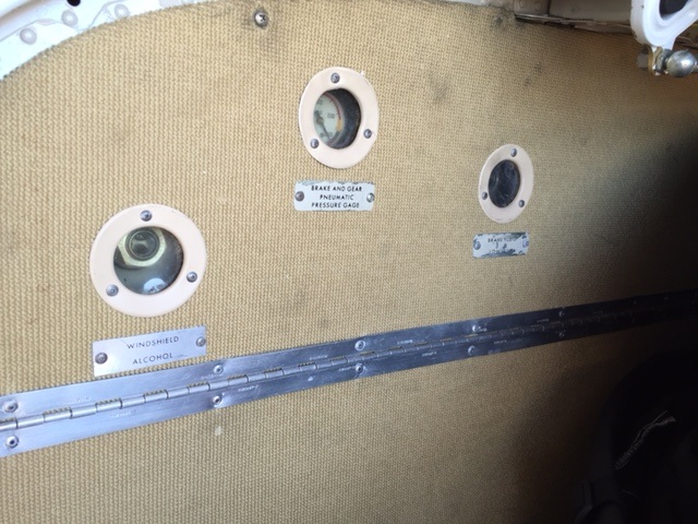
Leftmost gauge is the windscreen alcohol supply. It allows about 10 minutes of window clearing. The middle gauge is the emergency brake and gear pneumatic pressure gauge (should be 1800 - 2000 psi). The right hand side gauge is the hydraulic brake reservoir.
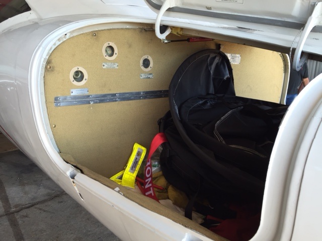
Next on the exterior are the two pitot tubes under the nose. Then there are two click latches for the baggage area on the door for each side. The Baggage area must be latched closed. If unlocked the doors open light will be illuminated in the cockpit. There is also a key lock on each side. There are a total of 5 doors on the plane (two nose baggage doors (below), main entrance door, emergency exit door (no cockpit indication it is open) and an aft compartment with some baggage space and lots of equipment and battery access). Pitot tubes are heated and checked along with the static ports on the side of the aircraft.
Next on the exterior are the two pitot tubes under the nose. Then there are two click latches for the baggage area on the door for each side. The Baggage area must be latched closed. If unlocked the doors open light will be illuminated in the cockpit. There is also a key lock on each side. There are a total of 5 doors on the plane (two nose baggage doors (below), main entrance door, emergency exit door (no cockpit indication it is open) and an aft compartment with some baggage space and lots of equipment and battery access). Pitot tubes are heated and checked along with the static ports on the side of the aircraft.
Next onto the panel
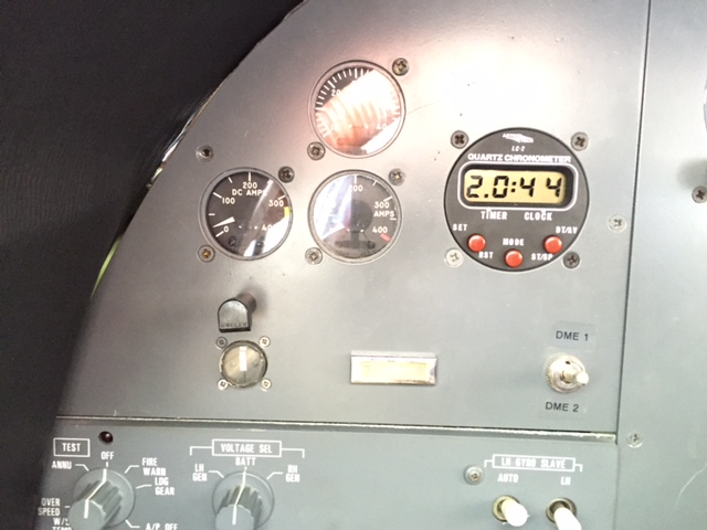
We start on the upper left. Key items here are the clock/timer and amperage gauges
Below these gauges are the test switch (far left) which tests the various aircraft systems (annunciator panel, overspeed warning, windshield overtemp, auto pilot off, landing gear warning, fire system). To the right of the test switch is the power selector (left gen, Battery or right generator). To the right of this is the gyro slave buttons.
Below these gauges are the test switch (far left) which tests the various aircraft systems (annunciator panel, overspeed warning, windshield overtemp, auto pilot off, landing gear warning, fire system). To the right of the test switch is the power selector (left gen, Battery or right generator). To the right of this is the gyro slave buttons.
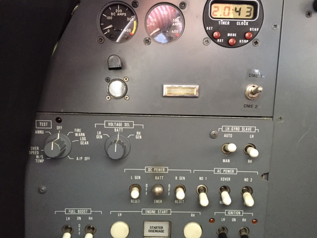
Below this panel is the general switch panel. The switches are laid out by system. The first row covers AC and DC power. DC Power side includes a 3 position switch for each generator ( left and right). Bottom position resets the generator. Middle position is off. Up position is on. The middle switch is also a 3 position switch for the battery - emergency, off and on. Emergency powers limited systems.
The AC switches include on/off switches for the No. 1 and No. 2 inverters. In between those two switches is the crossover switch which allows you to power the AC bus you want, in the event one inverter fails. The #1 inverter powers most AC operated things through the flight director bus. No 2 inverter powers weather radar and radio altimeter through the Radar AC bus.
The AC switches include on/off switches for the No. 1 and No. 2 inverters. In between those two switches is the crossover switch which allows you to power the AC bus you want, in the event one inverter fails. The #1 inverter powers most AC operated things through the flight director bus. No 2 inverter powers weather radar and radio altimeter through the Radar AC bus.
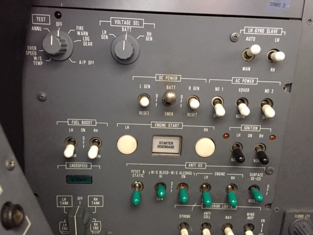
Next row down is the business end of the switch panel. To the left side are the 3 position switches for the left and right fuel boost pumps. The switch is normally in the Norm position (surprise). In the Off position, the fuel pump is off except during start and crossfeed operations. In the Norm position the pump will also come on automatically if fuel pressure in the applicable side fuel system is low. In off and Norm the pump is disabled if the throttle is in the cutoff position. The on switch, not surprisingly, turns the boost pump ON.
The two white circular buttons are the engine start buttons. Push the button momentarily to start the engines. Apply fuel to the engine at 12% N2 RPM by lifting the throttle over the cutoff latch to the idle position. And if all works out, the engine should be running after a few seconds. The Gen Off light should go out around 42% N2, if turned on (generally off if an APU is used to start). Bring the engine to about 51% N2 to use the generator power from the started engine to help start the other engine. If something goes awry, you can press the white starter disengage rectangular button between the start buttons. This button terminates the start sequence.
The right two switches are the left and right ignition switches. These switches are also left in Norm most of the time. In Norm ignition will come on during the start sequence and when anti-ice is on. The on-position will turn on the ignition. Ignition should be in the on position during take-off, landing and during turbulence. This action will potentially preclude a flameout.
Moving to the next row -
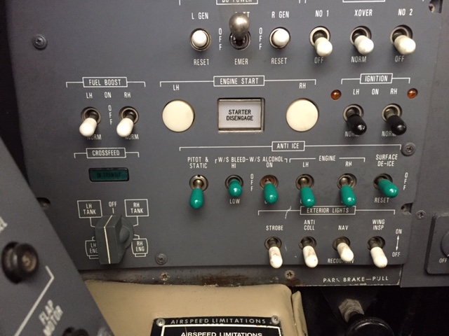
The green switches are for anti-ice systems. Leftmost switch is power for pitot static electrical heat. Next switch is a 3 (hi / off / Lo) position switch for windshield bleed air heat for deicing and defogging. Third switch from the left controls the alcohol back-up deicing system. You get about 10 minutes of alcohol icing protection. Next two switches turn on the bleed air heat to the engine and the electrically heated inboard leading edge panels on the wing (inboard silver section on the leading edge of the wing in the photo of the plane above). Final switch on the right activates the wing boots. The switch is spring loaded to off. Flipping it on starts a two six second cycle of the system. First 6 seconds inflates and deflates the boots on the vertical stabilizer and the left horizontal stabilizer. Second 6 second cycle inflates and deflates the boots on both wings and the right horizontal stabilizer.
The bottom row left side is the fuel cross feed fuel switch. The green light above is a crossfeed valve disagree light (e.g. lights if the valve is not in the commanded position). The white switches to the right are for the exterior lights - Strobe, anti-collision, Nav and wing leading edge (ice inspection) light.
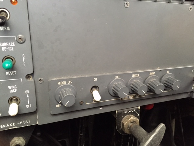
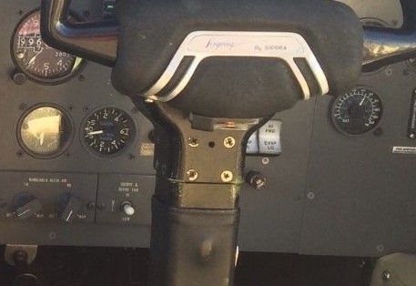
Below is the lower instrument panel behind the yoke. In the lower right you can see the wing inspection light switch. Immediately below that switch and partly cutoff in the picture is the parking brake handle. The T handle to the right is the control lock handle. This is largely unused as it can lead to damage if the aircraft is towed. Above the control lock is the cockpit light panel. The knob to the left is for the flood light (ceiling). Switch and other rheostat switches control the instrument panel lights.
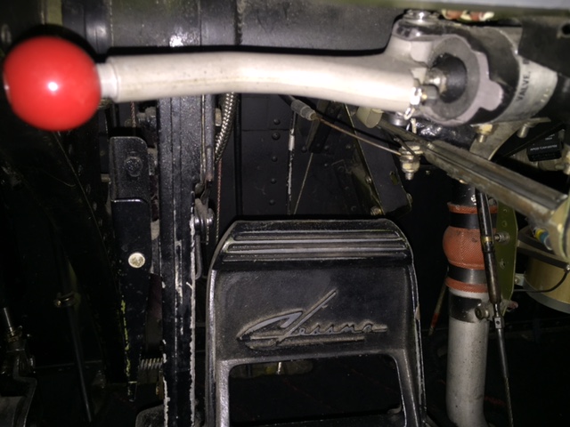
To the right of the control lock T handle you can see a red knob below the panel. This is the emergency brake which applies accumulator pressure to the brakes. You have 10 applications. Can't be used with normal brakes. A better picture of the handle is below this picture.
The bottom row left side is the fuel cross feed fuel switch. The green light above is a crossfeed valve disagree light (e.g. lights if the valve is not in the commanded position). The white switches to the right are for the exterior lights - Strobe, anti-collision, Nav and wing leading edge (ice inspection) light.
Below is the lower instrument panel behind the yoke. In the lower right you can see the wing inspection light switch. Immediately below that switch and partly cutoff in the picture is the parking brake handle. The T handle to the right is the control lock handle. This is largely unused as it can lead to damage if the aircraft is towed. Above the control lock is the cockpit light panel. The knob to the left is for the flood light (ceiling). Switch and other rheostat switches control the instrument panel lights.
To the right of the control lock T handle you can see a red knob below the panel. This is the emergency brake which applies accumulator pressure to the brakes. You have 10 applications. Can't be used with normal brakes. A better picture of the handle is below this picture.
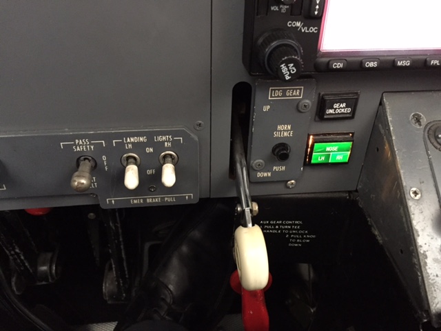
To the left of the emergency brake handle are: (1) passenger warning sign switch (silver to the left side); and (2) left and right landing lights. These are on the main gear and will turn themselves off when the doors close, but the practice is to turn them on and off with the gear.
Next to the light switches is the gear handle (white circular knob). Pull it out and then up to stow the gear or pull out and down to lower the gear. When the gear is locked down you will see the three green lights (one for each gear). While the gear is unlocked / in transit the red light above (gear unlocked) light will illuminate. To the right of the gear handle is the horn silence button. It will silence the horn if you bring power back before the plane is in the landing configuration.
Gear doesn't work - No problemo. The red knob visible below the round white gear knob is the emergency gear release. Pull the handle out and the gear locks are released. Yaw the aircraft right and left for a few seconds to let the wind catch the gear and pull it all the way down. Then there is an inner red knob (barely visible behind the handle). After the gear is down pull this out to use nitrogen to lock the gear down in place.
Next we will look at the center console. I ignore the pilot's main instruments as I was second in command, which is the more important position. When I am PIC I will add that part, as it will likely seem more important!!
Ok - there is a bunch of stuff here (above). Starting in the top left corner
The black knob control the cabin climb and descent pressurization rate.
The gauge shows the cabin altitude. To the upper right is the cabin differential pressure gauge. In the photo below you can see the cabin altitude and cabin differential pressure gauges.
The switch under the red guard is the cabin pressurization dump valve.
Gray knob to the right is the cabin temperature controller. The silver switch to the left and slightly below the knob is the manual temperature control.
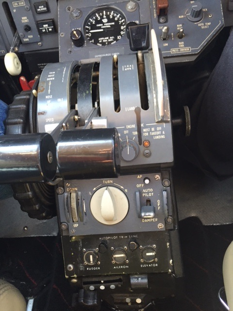
To the left of that, the black paddle is the flap controller. Push the knob in gently to move out of the up and mid-position gates and slide to the desired position. White stick to the left of that is the flap position indicator.
To the left of that are the left and right throttles. The bards sticking out towards the bottom allow you to move the throttles in and out of the fuel cut-off position at the beginning of the travel range.
The big black wheel to the left is the elevator trim control. Trim is important on this plane. The white stick to the right is the trim indicator.
The speed brake switch in on the control stand just to the left of the left throttle. Is is a spring to the center switch.
To the right of the throttle is the pressurization source selector. You can choose Off (no bleed air), ground (2x bleed air from the right air cycle machine (right engine on) on the ground for added cooling. Orange light above will illuminate in ground position.); Left (left side bleed air only), Both (both engines supply bleed air - normal position), RH (right side bleed air only); and Emer (gets hot noisy quickly with pressurization controlled by left throttle).
The black knob control the cabin climb and descent pressurization rate.
The gauge shows the cabin altitude. To the upper right is the cabin differential pressure gauge. In the photo below you can see the cabin altitude and cabin differential pressure gauges.
The switch under the red guard is the cabin pressurization dump valve.
Gray knob to the right is the cabin temperature controller. The silver switch to the left and slightly below the knob is the manual temperature control.
To the left of that, the black paddle is the flap controller. Push the knob in gently to move out of the up and mid-position gates and slide to the desired position. White stick to the left of that is the flap position indicator.
To the left of that are the left and right throttles. The bards sticking out towards the bottom allow you to move the throttles in and out of the fuel cut-off position at the beginning of the travel range.
The big black wheel to the left is the elevator trim control. Trim is important on this plane. The white stick to the right is the trim indicator.
The speed brake switch in on the control stand just to the left of the left throttle. Is is a spring to the center switch.
To the right of the throttle is the pressurization source selector. You can choose Off (no bleed air), ground (2x bleed air from the right air cycle machine (right engine on) on the ground for added cooling. Orange light above will illuminate in ground position.); Left (left side bleed air only), Both (both engines supply bleed air - normal position), RH (right side bleed air only); and Emer (gets hot noisy quickly with pressurization controlled by left throttle).
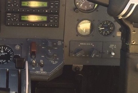
In the photo above you can see the cabin altitude and cabin differential pressure gauges. Below those are the windshield bleed are valves controls. They are connected to the valve so some effort is required to turn them.
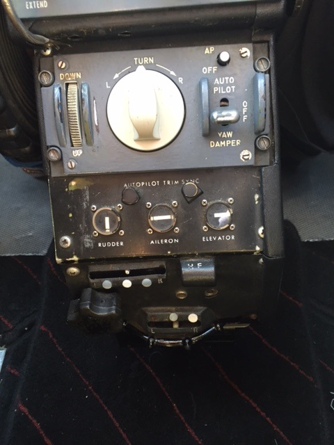
Below are autopilot controls and aileron and rudder trim. See photo below.
Below are autopilot controls and aileron and rudder trim. See photo below.
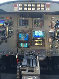
Next up are the annunciators and engine gauges at the upper center of the instrument panel
Red lights on the side are the engine fire lights. When illuminated (fire detected) push the red button to arm the extinguisher bottles (white switches below the red ones). Once armed either bottle can be used to extinguish either engine. Just push the white button for the bottle you want. The bottles (containing freon, I think) are located inside the aft compartment look straight up and slightly forward and you will see the two silver bottles.
Below are the engine gauges (see pics below). Red and orange rectangular lights to the left of the engine instruments are the master warning and master caution lights.
Below that on the left is the comm panel and Garmin 530 and Garmin 430 GPS Navcom's. On the right side is a Nav screen and below that are two transponders.
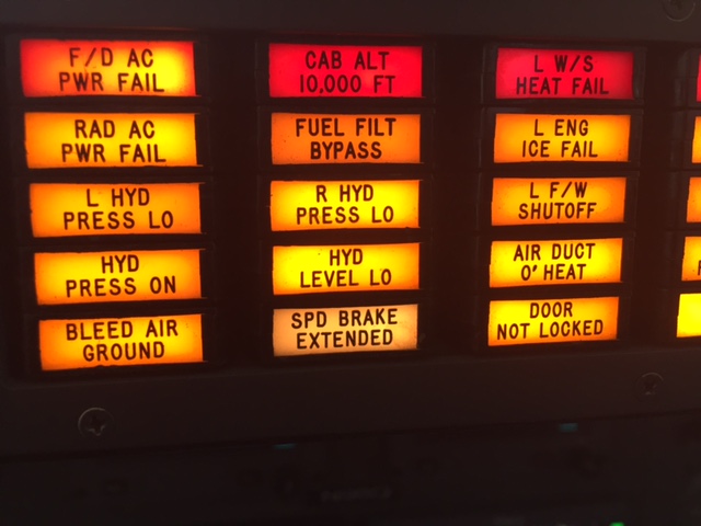
Annuciator Indications are as follows -
F/D AC PWR FAIL - Inverter No. 1 has failed or under/over voltage (<90 or >130 VAC) or inverter switch off
RAD AC PWR FAIL - Inverter No. 22 has failed or under/over voltage (<90 or >130 VAC) or inverter switch off
L / R HYD PRESS LO - Hydraulic pressure low on respective system - Pressure below 1350 PSI or >25 psi differential between pumps
HYD PRESS ON - momentary light that comes on when the hydraulic system is pressurized (something hydraulic is being used). When nothing being used the system goes to 60 psi.
BLEED AIR GROUND - Pressurization switch turned to GND position to double the pneumatic pressure to the right side air cycle machine
CAB ALT 10,000 - Cabin altitude is >10,000'
FUEL FILT BYPASS - Either or both fuel filters are approaching or are being bypassed due to flow restriction (3.5 - 4.0 psi differential)
HYD LEVEL LO - Hydraulic fluid has dropped below the refill level of .2 gallons. You can see the actual fluid level on the ground in the aft compartment - look up and to the left and you will see a steel rod inside a tube with 3 markings - refill / full and over-fill. Legends are hard to read, however, you just have to know what they are. Fluid refill is from the bottom of the lane through a pressurized can of fluid.
SPEED BRAKE EXTENDED - Both speed brakes are fully extended. Speed brake switch is a momentary on/off and is located on the center console.
L / R W/S HEAT FAIL - Windshield heat has failed
L/ R ENG ICE FAIL - potential causes (i) cowl or stator valves didn't open; (ii) cowl temperature is <77°c; (iii) inboard wing leading edge (silver portion) <16°c; (iv) failure of one or more wing leading edge heating elements; or (v) failure of the temperature controller or leading edge heater controller (light will cycle on and off with this). May come on when the system is first turned on until surfaces heat up.
L/R F/W SHUTOFF - This is bad - Indicates that fuel and hydraulic system valves at the firewall have been closed after the fire switch was actuated. Can be reset by resetting fire switch.
AIR DUCT O' HEAT - Air in the air duct just past the mixing manifold (Manifod can be seen in the aft compartment) is too hot >135°c
DOOR NOT LOCKED - One or more doors was not locked (can be one or more) - (i) L/R nose baggage doors; (ii) main cabin door; and (iii) aft compartment. System does not monitor the emergency exit door mid cabin n the right side. Have to check that visually.
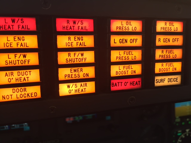
EMER PRESS ON -Pressurization switch in emergency position (switch is on the right side of center column) or A/C Overheat.
W/S AIR O' HEAT - Indicated either (i) Bleed air to the windshield is too hot or (ii) electrically controlled bleed air valve in the tailcone did not close with the switch off. Manual valves are also located at the bottom of the co-pilots side for each side of the windshield.
L/R OIL PRESS LO - Engine oil pressure <35 psi. Normally on before start.
L/R GEN OFF - Generator is off-line. Can be due to (i) Gen switch off; (ii) reverse current; (iii) fire switch / engine shutdown; (iv) over-voltage; or (v) feeder (differential) fault.
L/R FUEL PRESS LO - Low pressure side of fuel system has lo pressure (< 5 psi)
L/R FUEL BOOST ON - L or R fuel boost pump is operating- (i) switch is on; (ii) during engine start; or (iii) fuel cross-feed on
BATT O' Heat - Flashing light batt temp >71°c; Steady light batt temp >63°c but less than 71°c
SURF DEICE - illuminates while boots are inflated - will light once during each 6 second cycle
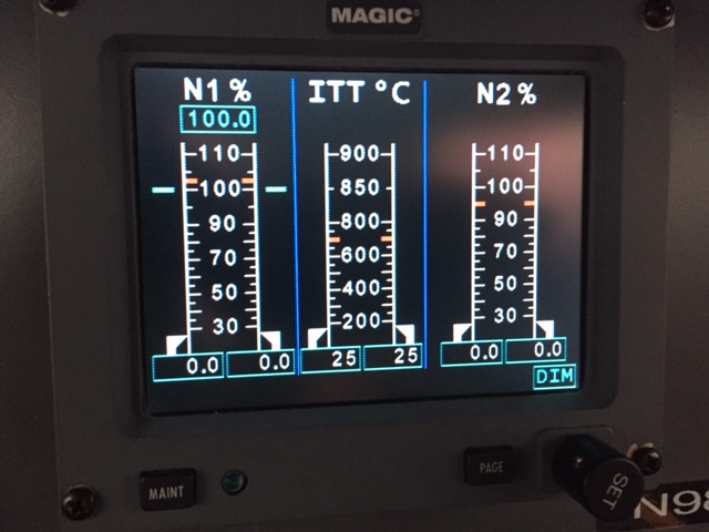
This engine instrument panel is at the top center of the panel, just below the annunciators. Left side instrument cluster shows N1, N2 and ITT, these are the main power parameters. When operating, the gauges have green indicator vertical lines. They remain green until the performance enters a warning area. Redlines are also shown.
W/S AIR O' HEAT - Indicated either (i) Bleed air to the windshield is too hot or (ii) electrically controlled bleed air valve in the tailcone did not close with the switch off. Manual valves are also located at the bottom of the co-pilots side for each side of the windshield.
L/R OIL PRESS LO - Engine oil pressure <35 psi. Normally on before start.
L/R GEN OFF - Generator is off-line. Can be due to (i) Gen switch off; (ii) reverse current; (iii) fire switch / engine shutdown; (iv) over-voltage; or (v) feeder (differential) fault.
L/R FUEL PRESS LO - Low pressure side of fuel system has lo pressure (< 5 psi)
L/R FUEL BOOST ON - L or R fuel boost pump is operating- (i) switch is on; (ii) during engine start; or (iii) fuel cross-feed on
BATT O' Heat - Flashing light batt temp >71°c; Steady light batt temp >63°c but less than 71°c
SURF DEICE - illuminates while boots are inflated - will light once during each 6 second cycle
This engine instrument panel is at the top center of the panel, just below the annunciators. Left side instrument cluster shows N1, N2 and ITT, these are the main power parameters. When operating, the gauges have green indicator vertical lines. They remain green until the performance enters a warning area. Redlines are also shown.
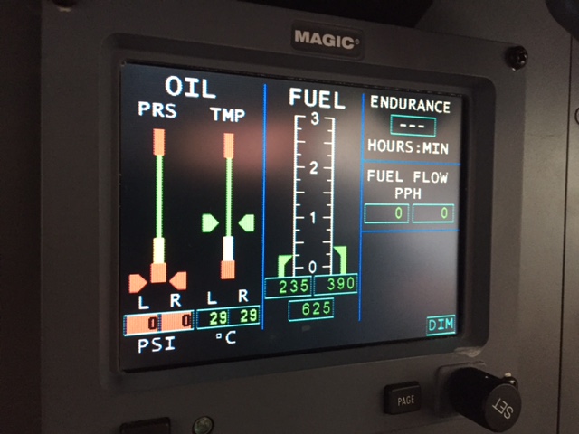
Below is the second engine gauge (to the right side of the above gauge) set showing L and R oil pressure and L and R fuel levels
Right side shows endurance and fuel flow.
Right side shows endurance and fuel flow.
Below -
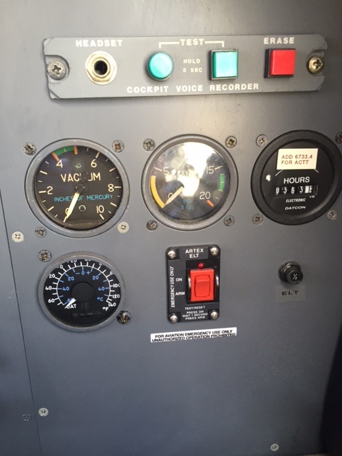
This panel is to the right side of the instrument panel near the top.
The first strip of controls is for the cockpit voice recorder.
Next to the left side in the second row is the vacuum gauge which operates the stand-by ADI.
In the middle of the second row is the oxygen tank(s) pressure.
Hobbs meter is to the right.
Bottom row left side is the outside air temp gauge and ELT switch.
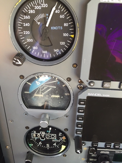
Below
Top is airspeed indicator
Middle is vacuum operated ADI
Bottom is an Altimeter
To the right (top) EADI and below that is an EHSI.
Top is airspeed indicator
Middle is vacuum operated ADI
Bottom is an Altimeter
To the right (top) EADI and below that is an EHSI.
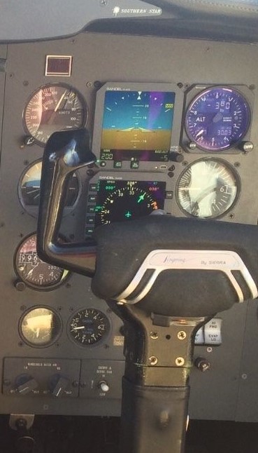
Above is a picture of the EADI and EHSI. To the left and above the EADI is the Master Caution red warning light.
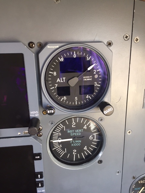
Below at the top of the picture is an altimeter and below that a VSI.
To the left (top) EADI and below that is an EHSI also shown in the picture above.
Below at the top of the picture is an altimeter and below that a VSI.
To the left (top) EADI and below that is an EHSI also shown in the picture above.
Last, but not least below is a picture of the climate control white rocker switches behind the co-pilot's yoke.
YEAH
